---
Connectors
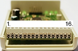
1. +12V power input
2. (-) GND (both ground terminals are internally connected together)
3. Start-up input
4. +5V power output
5. Analog input 1
6. Analog input 2
7. Analog input 3
8. Analog input 4
9. Analog input 5
10. Analog input 6
11. Analog input 7
12. Analog input 8
13. Digital input 1
14. Digital input 2
15. Digital input 3
16. (-) GND (both ground terminals are internally connected together)
---
Initial setup
Minimal connection to operate the device is 12V power supply.
Connect 12V power supply to the terminals:
+ = battery + terminal
GND = battery - terminal.
Note:
Do not use chassis, frame or subframe grounding points.
Use direct wire; to battery GND.
It is preferred to take the supply from the 12V battery using separate wires or other 'clean' power supply.
An 1A fuse in the battery end of the positive supply (in series) is recommended
to protect the wiring.
The device has an internal protection for electronics and 5V output, but higher
than 100mA load from the output can cause false analog input readings.
Note:
Install RaceDAC as close as you can to the receiving device (mobilephone/PC/laptop/etc).
To maximise RF-signal quality; leave ~50 mm space between RaceDAC and any flat metal surface.
These are common BlueTooth and RF related issues, not just RaceDAC specific issues.
Also, install RaceDAC; the side with the screws facing down; because then BT-antenna is
facing upwards.
---
Power supply input protection
Power supply input has a voltage protection circuit against electrostatic discharges or other voltage spikes. Continuous high positive (higher than 16 V) or any negative input voltages (lower than -0.5 V) may cause internal fuse operation, device malfunction or even failure if very high voltage is applied.
Internal fuse is a thermal type (PTC) and it is rated to 0.5A.
If the fuse is 'blown', device power supply is internally kept disconnected
until the failure cause is removed.
It is also recommended to disconnect the power supply and let the fuse to cool down
(min. 15 sec.) before reconnection and restart.
---
On/Off-pushbutton
Press On/Off-pushbutton gently (for approx 1 second) to start the device.
---
Start-up input
12V signal connected to this input starts the RaceDAC. When signal is removed
or level is low, RaceDAC will go off.
On/Off-pushbutton is disabled when start-up signal is on. This enables that the
RaceDAC can be placed more freely and operated with a remote switch, which gives 12V
signal to the RaceDAC start-up terminal.
---
Automatic start-up
Automatic start-up can be enabled with a jumper inside the RaceDAC enclosure:
Automatic start-up -jumper
Then the device goes automatically on when the main 12V power supply is available.
---
5 V Power output
5 V / 100 mA output is available for external sensors or devices. Output is internally
regulated and it has approximately 2.5ohm source impedance.
If 100 mA is drawn from the output, voltage level may drop to 4.75 V.
Shorting the output or taking too much current may cause device malfunction
(short current spikes) or 'blowing' the internal fuse (longer period of overcurrent).
---
Dip-switches
Analog input range is selected using dip-switches on the printed circuit board.
If the switch is ON, 0-5V range is selected.
When the switch is OFF, input range is 0-15V.
---
Analog inputs
Analog inputs have two ranges of operation:
Factory calibrated 0-5V input range and uncalibrated 0-15V range.
Analog input impedance is about 106 kohm with 0-5 V range and about 320 kohm
with 0-15V range.
This high impedance makes the device sensitive to externally coupled noise.
Keep the input wiring as short as possible and far from possible noise sources
(spark plugs, ignition coils, fuel injectors, relays etc).
It is also recommended that the sensor source impedance is less than 1000 ohm.
All unused analog input channels can be connected to one of the ground terminals to prevent noise at the output.
With default settings (out of the box) output readings are 0...5000 when measured
voltage is 0...5V.
For example: When measured voltage is 2.35V, output reading is 2350.
You can adjust all channel output readings by using user adjustment parameters.
You can also use lookup table for analog channel/ channels.
---
Analog reading conversion using lookup table
There is option to use lookuptable to convert analog input readings 0..5000
to any output value between 0...65535.
This option is useful when connecting for example thermal, or
lambda/ air-to-fuel-ratio, or other non-linear sensors to RaceDAC.
User can define/ write two different lookup table.
Same lookup table can be used for multiple analog channels (usefull for example
if you have multiple identical thermal sensors).
To enable lookup table operation, user must change analog input channel mode
to lookup1 or lookup2.
User must define/ write the lookup table point number count and table in-out-points.
Minimum number of points is 2 and maximum 16 points per table.
Points must be defined in ascending order of the input reading.
Input reading stepping does not have to be constant. So you can use whatever
input values (0...5000) you like, as long as they are in ascending order.
But it is recommended that the first point input value is always 0, and the last
point input value is between 5000 and 6000.
Between the points, RaceDAC uses linear regression to calculate the output.*
User adjustment parameters (u.offset etc.) are not used when analog channel is defined to use lookup table.
Note: Input values are "millivolts".
---
Analog input protection
All analog inputs have separate input voltage protection circuits against electrostatic discharges or other voltage spikes. Continuous high positive (higher than 16 V) or any negative input voltages (lower than -0.5 V) may cause false output readings, other device malfunction or even failure.
---
Digital inputs
RaceDAC device has three digital inputs that are internally matched to 0-5 to 0-15V digital signal ranges.
Operation mode 0 = RPM measurement
Time period between successive rising input edges is measured using high frequency
counter and result is converted to RPM value.
Operation mode 1 = Frequency measurement
Operation is about the same as in RPM measurement, now the time period is
converted to Hz value and the result is multiplied by 10. Frequency resolution
is then 0.1Hz. Output reading 1000 means frequency 100.0 Hz.
Operation mode 2 = Impulse counter
Each edge is counted, overflow to 0 after 65535.
Operation mode 3 = Digital status input
Digital input pin status is read directly
Note: With default setting; predivider = 1; RaceDAC can measure up to;
30 000 RPM in RPM-mode, 0-3000Hz in Frequency-mode, or 65 535 pulses in
Impulse counter-mode.
That is because software can not handle bigger numbers, but:
You can use predivider to widen the measuring range. Then software is able to
handle the signal (up to 0-3000000 RPM/ 0-60000.0 Hz).
Also, in operation modes 0 and 1, user can change the output reading range using
u.offset, u.gain and u.divisor parameters.
Note: Predivider and user divisor are two separate parameters.
---
Digital input timeout
There are a timeout parameters for each digital input. If there are not any input impulses during the timeout time (factory default is 2 seconds), the frequency reading is reset to 0.
---
Digital input protection
Digital inputs have similar protection circuits as analog inputs.
Input impedance is lower than in analog inputs, about 20kohm, but inputs are
still sensitive to noise spikes or other transients.
In rpm, Hz and counter modes, inputs are rising edge sensitive,
and in status mode input status is read directly from the input terminal.
Threshold level is about 3.5V for edge and high level status detection.
---
Start-up
To start-up the device:
Use On/Off-pushbutton, or 12V start-up signal, or Automatic
start-up.
Red led near the button will go on (indicating that the internal 3.3V
power supply is on).
Initially, both bluetooth leds start to blink, and after the module is
initialised, only the second led from left is blinking.
Then the device goes to firmware update mode for a while (user can configure
the wait time for firmware update). The third led is on during the firmware update time.
After the firmware update time has passed, third led goes off and bluetooth link leds
start to blink again.
After few seconds, the third led should begin blinking with
rather high frequency indicating that the main software loop is running.
Total RaceDAC start-up time is less than 10 seconds (plus the user configurable
firmware update wait time, see firmware update chapter for further info).
---
Stand-by
Press on/off button gently (3 sec.). All indicator leds will go off and
when you stop pressing the button, the device will go to stand-by.
Or if you are using start-up input signal; when signal level is low, the device
will go to stand-by.
---
Initial connection
PC with bluetooth connectivity and a terminal program is needed for configuration.
At first, PC and RaceDAC bluetooth devices must be paired with default
pin-code 1234.
Then PC will install serial port device drivers, and after a while, it
informs usually one or two serial port numbers that can be used to connect to
the RaceDAC:
For example "COM4", or "COM4" and "COM5". If two COM-ports are given, use the
one with smaller number, in this case "COM4", to communicate with RaceDAC.
Open terminal program. (See Links for alternative Client/Terminal SW's)
For example: By default Windows XP PC has a sw called HyperTerminal
(Click: Start - Programs - Accessories - Communications - HyperTerminal)
The first time HyperTerminal is started; it asks for a phonenumber; input anything,
it is not needed, it is just a happy windows -feature on the first run.
Then give any name and icon for connection, and click "Ok".
Connect using the COM-port which window installed for RaceDAC, for example COM4.
You may have to disconnect "the call" first before you are allowed to check the
parameters. Click "Disconnect"-icon, or choose "Call" - "Disconnect".
Set communication parameters to:
- 115200 baud
- 8 data
- 1 stop
- No parity
- No handshake
- Port "COM4" (or whatever you got at the device driver installation phase)
Open the connection (Click "Call"-icon, or choose "Call" - "Call"; and HyperTerminal
will connect to RaceDAC by using port COM4).
And you should see data stream coming from the RaceDAC device to the terminal
program screen ($RC1... or $RC2... message lines).
---
CMD-mode
Now you can enter to cmd-mode by writing letters:
CMD
into the terminal window and pressing enter.
Note that there is no echo ("CMD" is not displayed on the screen) at this phase
of communication. So just write the letters and press enter.
Entering to the cmd-mode is indicated by a reply string:
"RaceDac cmd mode" and the data acquisition is stopped.
Now you can send configuration commands (press enter after each command).
Note that there is no line edit function in the command interpreter: So if you type something wrong or give wrong parameter value, you must press enter and rewrite the whole command.
---
Commands
Enter to cmd mode:
CMD
Enter to data acquisition mode:
DAC
Read firmware id:
ID
Read output message frequency:
RCFREQ
Returns output message frequency: 1, 2,5, 10, 20, 50 or 100 (Hz)
Set output message frequency:
RCFREQx
x is 1, 2,5, 10, 20, 50 or 100 (Hz) to set new value.
Any other value sets frequency to default: 10 (Hz)
Read data transfer mode:
RCMODE
Returns output data transfer mode 1 = $RC1 and 2 = $RC2
Set data transfer mode:
RCMODEx
where:
x is 1 for $RC1, and 2 for $RC2
Read factory parameters:
FRx
where x is analog input channel number
returns f.offset, f.gain and f.divisor values
---
User adjustment
Calculation formula, analog channels:
Calibrated value = Factory calibrated measured value in Volts * 1000 = millivolts
Output result = [(calibrated value - u.offset ) * u.gain] / u.divisor
Default output reading is in millivolts.
if output result is more than u.max ; output result = u.max
if output result is less than u.min ; output result = u.min
Calculation formula, digital channels:
Output result = [((calibrated value/ predivider) - u.offset ) * u.gain] / u.divisor
if output result is more than u.max ; output result = u.max
if output result is less than u.min ; output result = u.min
---
Default user parameters
Default parameters for all analog channels are:
User offset: 0
User gain: 5
User divisor: 5
User min: 0
User max: 32767
User averaging mode: 0 (= No)
Default parameters for both digital channels are:
User offset: 0
User gain: 1
User divisor: 1
User min: 0
User max: 32767
User averaging mode: 0 (= No)
---
User adjustment commands
Read user parameters:
URx
Where: x is channel number; 1...8 for analog channels 1...8, and 11...13 for digital channels 1...3
returns u.offset, u.gain, u.divisor, u.min, u.max and averaging mode values
Clear user parameters:
UCLEAR
Clears all user parameters, and sets all values to default values.
See above part for default values.
User offset read:
UORx
Where: x is channel number: 1..8 for analog inputs (1...8), and 11...13 for digital channels 1...3
User offset write:
UOWx,uoffset
Where: x is channel number: 1..8 for analog inputs (1...8), and 11...13 for digital channels 1...3
uoffset range: -32768...32767
User gain read:
UGRx
Where: x is channel number: 1..8 for analog inputs (1...8), and 11...13 for digital channels 1...3
User gain write:
UGWx,ugain
Where: x is channel number: 1..8 for analog inputs (1...8), and 11...13 for digital channels 1...3
ugain range: -32768...32767
User divisor read:
UDRx
Where: x is channel number: 1..8 for analog inputs (1...8), and 11...13 for digital channels 1...3
User divisor write:
UDWx,udivisor
Where: x is channel number: 1..8 for analog inputs (1...8), and 11...13 for digital channels 1...3
udivisor range: 1...32767
User max and min parameters read and write:
Use EEPROM write commands and eeprom address map:
104..111 (u.max) for analog channels 1...8
112..113 (u.max) for digital channels 1...2
114..121 (u.min) for analog channels 1...8
122..123 (u.min) for digital channels 1...2
User min range: 0...+32767 (u.min)
User max range: 0...+32767 (u.max)
---
Lookup table commands
Lookup table read:
LTRz
Where: z is lookup table number 1...2
Returns number of points in lookup table z, and lists points:
point:in,out
Lookup table points count write:
LNWz,n
Where: z is lookup table number 1...2
n must be in range 2..16
Lookup table point write:
LPWz,n,x,y
Where:
z is lookup table number 1...2
n is lookuptable point number 1...16
x is input reading 0...5000
y is output reading 0...65535
Points must be sorted in ascending order of x It is recommended that the first x is always 0 and the last x is between 5000 and 6000
---
Channel-mode commands
Analog channel mode read:
AMRx
Where: x is analog channel number 1..8
Analog channel mode write:
AMWx,y
Where:
x is analog channel number 1..8
y is mode: 0 = normal, 1 = lookuptable1, 2 = lookuptable2
Digital channel mode read:
DMRx
Where: x is digital channel 1...3
Digital channel mode write:
DMWx,y
Where:
x is digital channel 1...3
y is mode: 0 = rpm, 1 = Hz, 2 = count, 3 = status
Averaging mode read:
UARx
Where: x is channel number: 1..8 for analog channels (1...8), and 11...13 for digital channels 1...3
Returns user averaging mode:
0= no average (new measurement in each cycle)
1= simple rc type average (oldresult+new)/2)
2= average of 2 measurements (new+previous)/2)
Averaging mode write:
UAWx,y
Where:
x is channel number: 1..8 for analog channels (1...8), and 11...13 for digital channels 1...3
y is user averaging modes:
0= no average (new measurement in each cycle)
1= simple rc type average ((oldresult+new)/2)
2= average of 2 measurements ((new+previous)/2)
---
Digital input timeout and predivider commands
Digital input timeout read:
DTRx
Where: x is digital channel 1...3
Digital input timeout write:
DTWx,y
Where:
x is digital channel 1...3
y is timeout value as multiples of 0.1s (10 = 10 * 0.1s = 1 second timeout)
Max timeout multipler value is 1000 (100.0 seconds).
Digital input predivider read:
DPRx
Where: x is digital channel 1...3
Digital input predivider write:
DPWx,y
Where:
x is digital channel 1...3
y is predivider value 1..1000
---
Memory map:
0 Program startup counter, incremented automatically after each device startup
1 Output message format: 1=RC1, 2=RC2, other=RC2
2 Message output frequency; allowed values: 1, 2, 5, 10, 20, 50 and 100 (Hz)
Requires hw reset to be effective.
3 Message baudrate: 0 = 115200, 1 = 57600, 2 = 38400, 3 = 19200, 4 = 9600
Limits also automatically highest message frequency to 100, 50, 50, 20 and 10Hz respectively
4 Digital input1 mode: 0=rpm, 1=Hz, 2=count, 3=status 5 Digital input1 timeout value: N*0.1seconds 6 Digital input1 predivider: 1..250
7..9 reserved
10 Digital input2 mode: 0=rpm, 1=Hz, 2=count, 3=status
11 Digital input2 timeout value: N*0.1seconds
12 Digital input2 predivider: 1..250
13..15 reserved
16..23 Analog input mode, channels 1...8: 0=normal, 1=lookup1, 2=lookup2
24..30 reserved for future use
31 Firmware upload wait time
---
Memory map: Factory calibration parameters
32..39 factory calibration f.offset values for analog channels 1...8
40..47 factory calibration f.gain values for analog channels 1...8
48..55 factory calibration f.divisor values for analog channels 1...8
56..63 reserved
---
Memory map: User parameter area
64..71 user offset adjustment values for 8 analog channels (u.offset)
72..73 user offset adjustment values for 2 digital channels (u.offset)
74..81 user gain adjustment values for analog channels (u.gain)
82..83 user gain adjustment values for digital channels (u.gain)
84..91 user divisor adjustment values for analog channels (u.divisor)
92..93 user divisor adjustment values for digital channels (u.divisor)
94..101 user averaging modes for analog channels 1...8:
0 = no average (result=new measurement in each cycle)
1 = simple rc type average (result=(oldresult+new)/2)
2 = average of 2 measurements (result=(new+previous)/2)
102..103 user averaging modes for digital channels 1...2:
0 = no average (result=new measurement in each cycle)
1 = simple rc type average (result=(oldresult+new)/2)
2 = average of 2 measurements (result=(new+previous)/2)
104..111 user max output limit values for analog channels 1...8
112..113 user max output limit values for digital channels 1...2
114..121 user min output limit values for analog channels 1...8
122..123 user min output limit values for digital channels 1...2
124..159 reserved for future use
---
Memory map: Lookup table area
160 analog lookup table1 points count
161 reserved
162..177 analog lookup table1 input value points
178..193 analog lookup table1 output value points
194 analog lookup table2 points count
195 reserved for future use
196..211 analog lookup table2 input value points
212..227 analog lookup table2 output value points
228..255 reserved for future use
---
EEPROM read:
ERx
Where: x is memory location 0..255
See the Memory map for related parameters
You can use EEPROM read command to read any EEPROM address.
---
EEPROM write:
EWx,y
Where:
x is memory location 0..255
y is data value as
unsigned int 0...65535 or
signed int -32768...32767
When using write command, you will get a reply, for example:
"EW1,1" will reply
"Eeprom addr 1: 147(147) => 1(1)"
indicating that you changed the old value 147 to 1 in address 1.
You can use EEPROM write command to any EEPROM address. So be careful when using this command.
---
Raw analog read:
RAx
Where: x is analog channel number
Will give raw, uncalibrated conversion result from analog channel
---
Calibrated analog read:
CAx
Where: x is analog channel number
Will give result after calibration and user adjustment from analog channel
---
Extra analog read:
XAx
1 = gnd reference
2 = 3v3 supply / 2 = 3700
3 = 1/11*12V supply = 2500
---
Factory calibration
NOTE:
Do not change the EEPROM factory calibration parameters unless you
are absolutely sure what you are doing.
For input range adjustment, use user parameter area in the
EEPROM (see the Memory map/ User adjustment part below).
12-bit A/D conversion output range gives output values ranging from 0 to
4095. Analog channels have an individual internal offset and some gain variation
that are compensated with factory calibration parameters.
Factory calibration offset adjustment range: -512...+512 (f.offset)
Factory calibration gain multiplier range: -32768...+32767 (f.gain)
Factory calibration gain divisor range: 1...+32767 (f.divisor)
Calculation formula:
calibrated result = [ ( raw value - f.offset ) * f.gain] / f.divisor
Calculation is made using long integer values but the result is truncated to 16- bit unsigned integer. The user must take care of the result overflow if improper parameter values are used. Analog channel specific calibration parameters are stored in the EEPROM memory.
By default, 0-5V input range is factory calibrated to output value range 0-
5000.
Default parameters are same for each analog channel:
f.offset 0
f.gain 12210 (=5000*10000/4095)
f.divisor 10000
Default parameters are changed during factory calibration and saved into the
following EEPROM memory locations:
32..39 f.offset values for analog channels 1..8
40..47 f.gain values for analog channels 1..8
48..55 f.divisor values for analog channels 1..8
---
Firmware update wait time
Set firmware update wait time:
FWUWx
x = firmware update wait time in seconds
Min. value is 0 (sec)
Max. value is 60 (sec)
Read firmware update wait time:
FWUR
Returns firmware update time value
---
Firmware update
RaceDAC has an internal firmware update function. Immediately after device reset or initial power up, factory programmed bootloader function reads expansion pin status between pins 1 and 2:
If they are shorted with a jumper, RaceDAC stays in the bootloader mode where it waits for the commands from firmware update program (PC terminal application). New firmware must be compatible with the bootloader or else the next firmware update cycle is not possible.
If the jumper is not installed, firmware waits for the update commands according to the firmware update wait time parameter and jumps then to the previously loaded application firmware. This wait time allows firmware update even without the jumper installation.
If user has configured wait time to 0, and there is no jumper, RaceDAC starts directly.
---
Firmware update procedure:
1) Disconnect 12V power supply.
2) If firmware update wait time parameter is long enough, jumper is not needed.
If you want to use jumper:
Open RaceDAC enclosure and install jumper:
Firmware-update-jumper
3) Connect power supply and start up the RaceDAC.
4) Go to the PC and locate your bluetooth serial port that is already paired with the RaceDAC (for example COM6), or do the pairing.
5) Locate flash.exe software and put new sw.hex -file in the
same directory.
For example; Make "rdac"-folder in your c:-drive root, and put flash.exe and
sw.hex files to that folder.
6) Open windows command prompt: Click "Start" - "Run..." Write "cmd" and click "Ok".
In command prompt window, go to your rdac -folder:
For example write "cd c:\rdac" and press enter.
Run flash.exe with filename and -i -option for bluetooth communication port, for
example:
flash sw.hex -iCOM6
7) Flash software prints messages during firmware download. If it finds an error, an "Assertion failed" or other message is generated indicating the source of the error and the program is terminated. For example if the communication port is reserved for another program.
8) After successful update: Disconnect power, remove jumper (if present) and close the enclosure.
9) Connect power supply.
10) Test the new software.
Note: You may need to change some eeprom parameters before and/or after the new firmware is loaded. See firmware specific update notes.